
Configuring CAN Receive & Modem Control in Bosch Racecon
To set up a CAN Receive from Modem:
For this operation you will have been supplied with a DBC file by the Control Support. Open your Racecon project and navigate in the Project window to the Logger or ECU you are trying to configure. Expand the dropdown by clicking on the plus sign. Go to the CAN node as determined by your wiring schematic and right click on CAN Input. Select the option Import from DBC File and import the Control DBC file you have been supplied with.
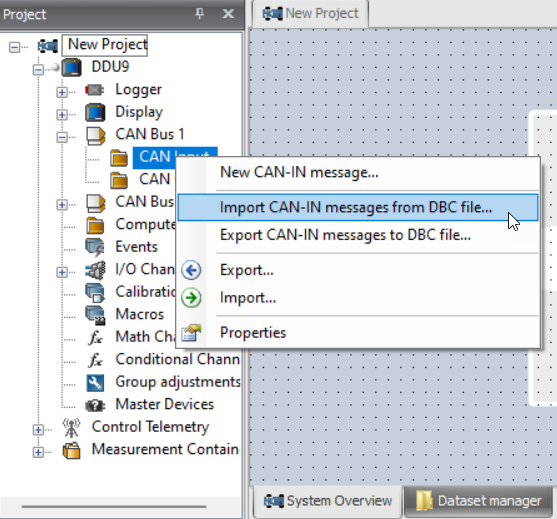
From the list of signals, select all channels apart from the ones in the Control message (0x610), this process can be simplified by clicking on the ID header to sort the list by CAN ID. Click OK. You will now be able to log modem channels and add them to the telemetry table for transmission.
To set up CAN Modem Control:
Create Channels for Modem Control (optional)
Open your Racecon project and navigate in the Project window to the Logger or ECU you are trying to configure. Expand the dropdown by clicking on the plus sign. Expand the Math Channels node with double click.
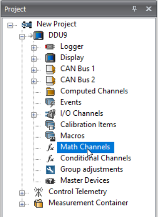
In the Math Channel configuration page click the Add channel and create either math or conditional channels for each of the channels you wish to use to control the modem, as defined in the document that accompanies the DBC file
For the suppress channel it is recommended that the logger allows transmission regularly for a short burst so that engineers can validate telemetry is working when the main transmission condition is not met. An example is given in the next section, please note that the RaceCon user interface mode must be set to Expert to access all screens below and that two channels are used to create the desired result.
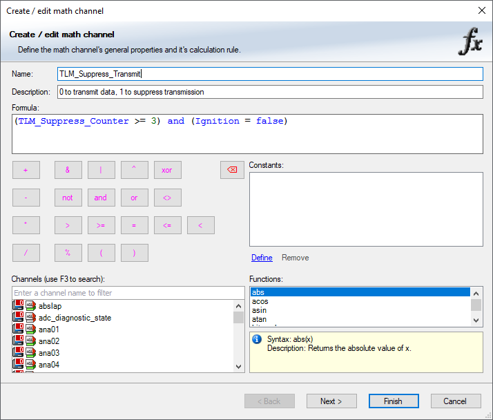
TLM_Suppress Maths Example
Create a counter channel to increment between 0 and 19
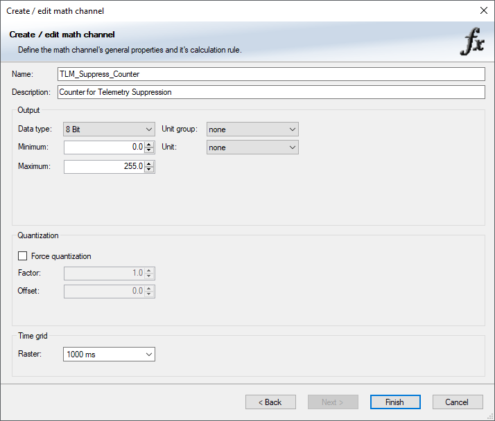
Set the counter channel properties to an 8 bit value that increments once a second
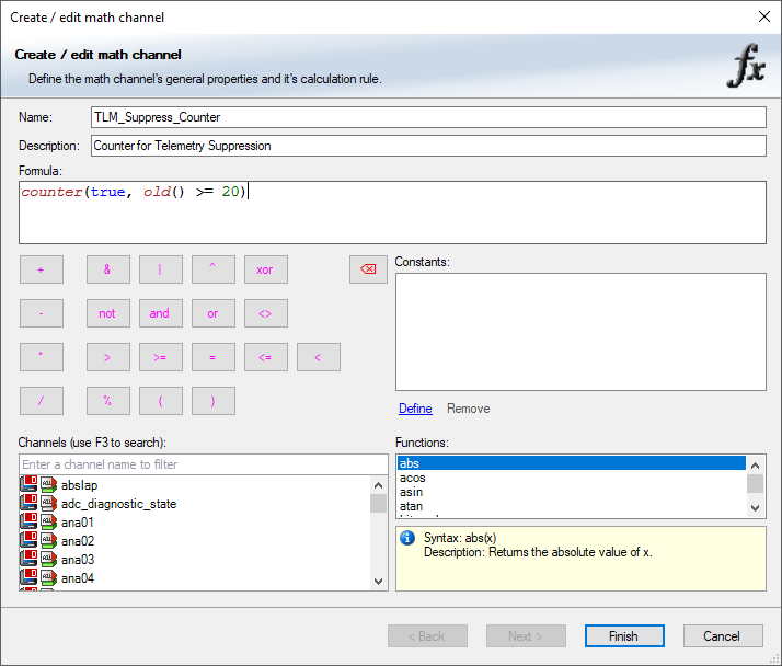
Create the TLM_Suppress channel that allows the transmission of telemetry for 2 seconds every 20 until a telemetry start condition is met, for example the ignition is switched on, at which point telemetry should flow all the time
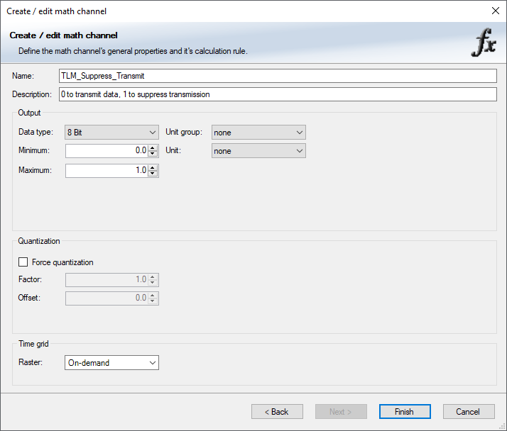
Set the channel properties to ensure it is an 8 bit value rendered on demand
Transmit generated channels to the modem
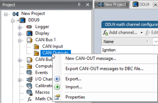
Open your Racecon project and navigate in the Project window to the Logger or ECU you are trying to configure. Expand the dropdown by clicking on the plus sign. Go to the CAN node as determined by your wiring schematic and right click on CAN Output. Select the option New CAN-OUT message.
Set the name and description to meaningful values and the CAN ID to the expected control message value, the default is 0x610. For each channel you wish to transmit click Add Channel and select the desired channel, set the channel information as per the DBC file.
Note: on later versions of RaceCon it is required that you change the representation to bit and limit the length to 7 or you can encounter issues with the signed 8 bit being set to 1 erroneously.
In the below example you can see the channels are all set to 7 bits in length
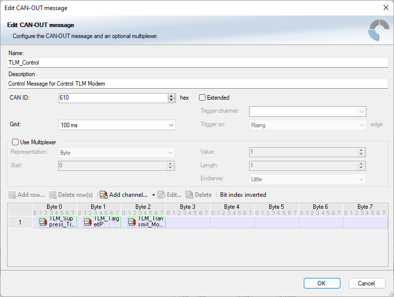
Once all the channels have been added Click OK